http://www.mynetworkinglabs.com/2012/11/packet-tracer-533-review-and-free.html
Scroll down to the Windows section, as shown below, and download the "Application + Tutorial".
There is an annoying Captcha that makes you open a page with ads.
Packet Tracer, with tutorials, is an 80 MB download. If you prefer not to download it, it is available in the S214 lab.
Once you have it downloaded, install it with the default options.
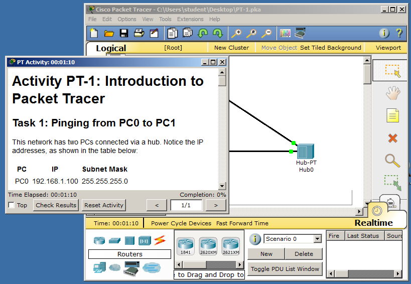
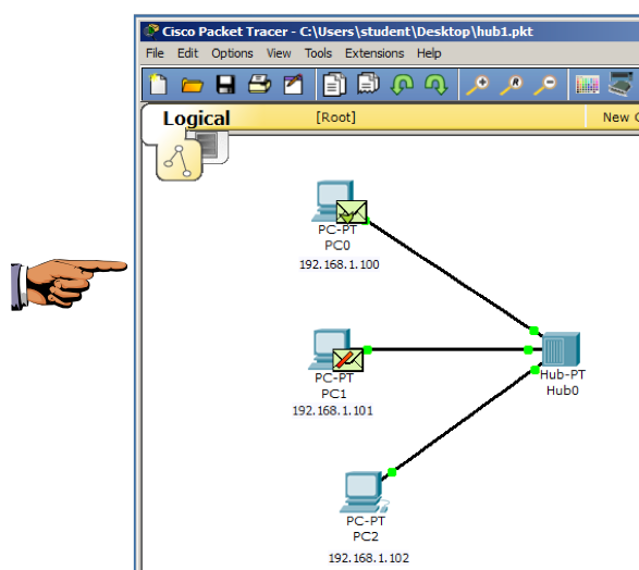
On your desktop, double-click the hub1.pkt file.
Activity PT-1 launches in Packet Tracer, as shown below:
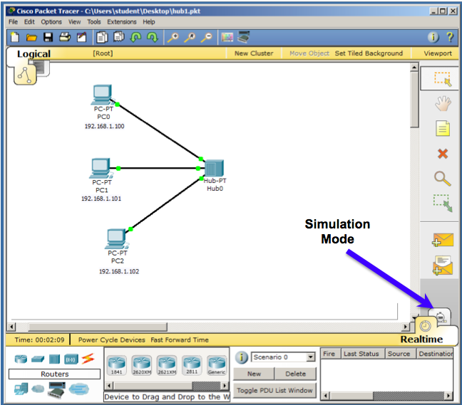
Click the "Simulation Mode" button, as indicated in the figure above.
An "event list" appears on the right, as shown below:
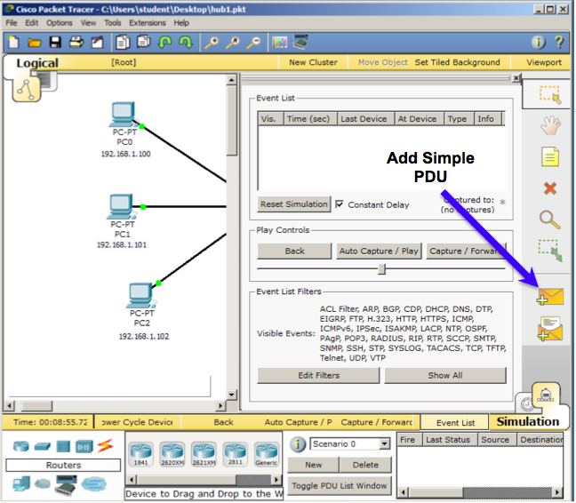
Click the "Add Simple PDU" button, as indicated in the figure above.
Then click on PC0.
Then click on PC2.
This launches a Ping packet from PC0 to PC2.
On the right side, click the "Auto Capture / Play" button.
Close the Event list, or move it out of the way, so you can watch the animation, as shown below.
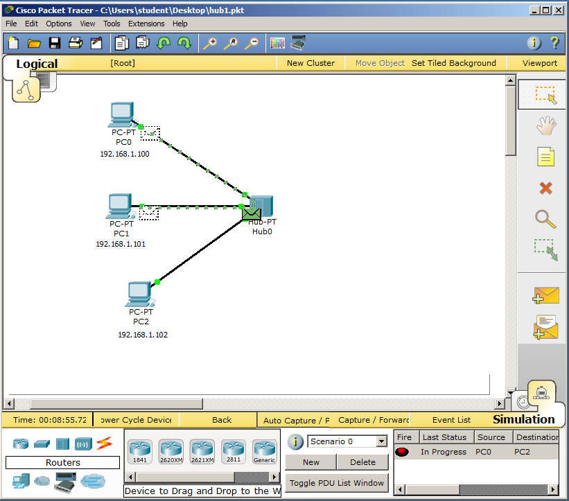
Notice that the single Ping sent from PC0 is delivered to both PC1 and PC2 by the hub.
When the simulation is complete, you should see the screen below, showing green envelopes on PC0 and PC1. There is a a green check mark on PC0 and a red X on PC1, but they flicker and may not appear in the image you capture.
Press PrntScrn to capture the whole desktop. Paste it into Paint and save it with the filename: "Proj 5a from YOUR NAME".
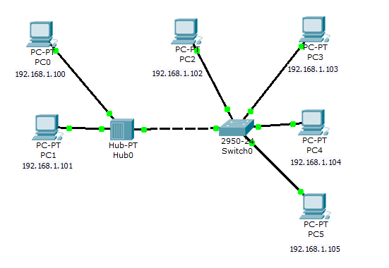
Launch the file in Packet Tracer. Wait for all the link lights to turn green.
Switch to Simulation Mode.
Click the "Add Simple PDU" button.
Then click on PC0.
Then click on PC2.
This launches a frame from PC0 to PC2.
Watch how it moves. The frame goes to the hub, then it is reproduced into three frames which go to PC1, PC2, and the Switch.
PC1 and the switch reject the frame, and PC2 accepts it and replies.
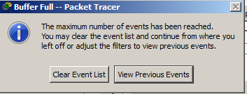
If a "Buffer Full" box pops up, as shown below, click "View Previous Events".
When the simulation is done, you see the screen below, showing that this ping reached two devices that rejected it: PC1 and the Switch.
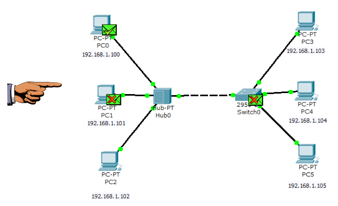
As you can see, the switch terminates the collision domain--if the switch receives a frame intended for a device on the left, it does not send it to any devices on the right.
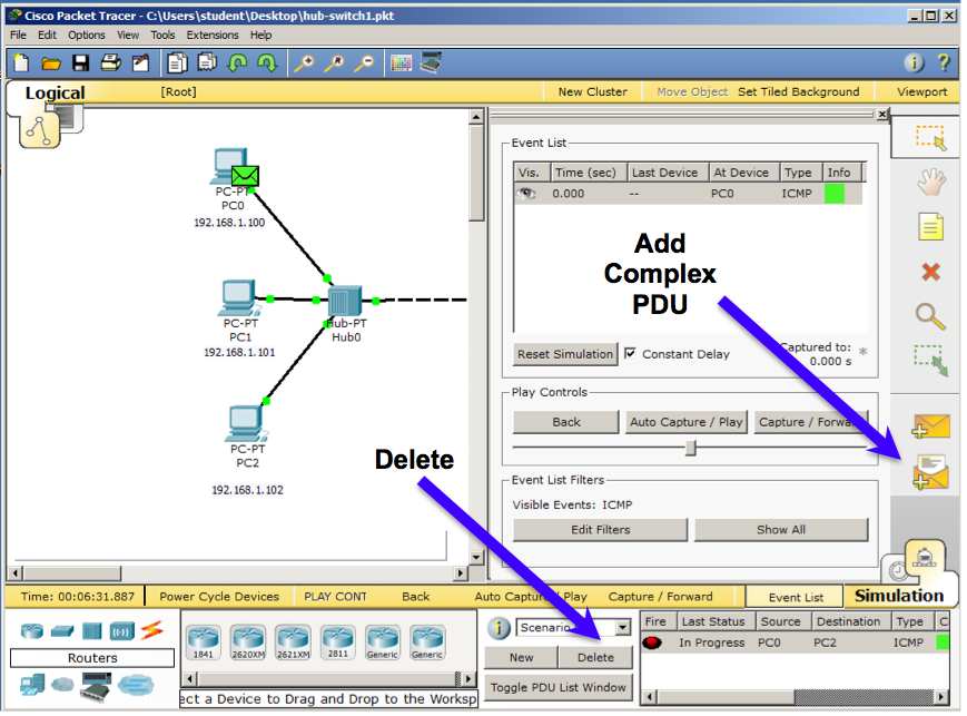
click the "Add Complex PDU" button, as indicated in the figure below.
Then click on PC0.
A box pops up asking for information about the packet. Fill in these values, as shown below:
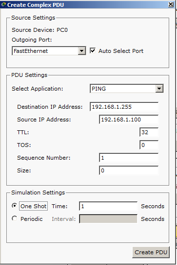
Click the "Create PDU" button.
Click the "Auto Capture / Play" button.
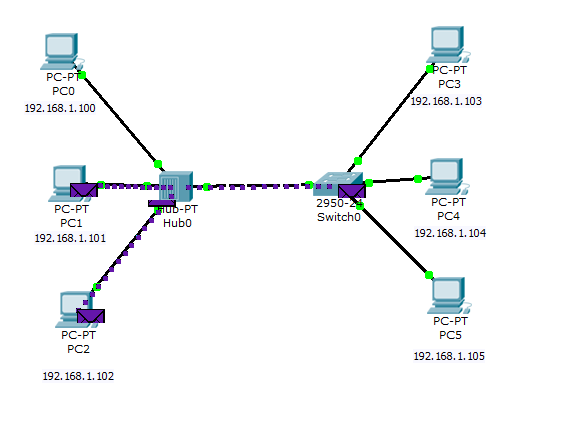
Watch the simulation. First the hub sends packets to PC1, PC2, and Switch0, as shown below:
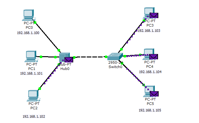
Then Switch0 sends packets to PC3, PC4, and PC5, as shown below:
If you didn't see those events, and want to replay the simulation, click the "Reset Simulation" button and then click the "Auto Capture / Play" button.
As you can see, broadcasts don't stop at a swich--the switch repeats those packets, because they are explicitly addressed to go to all devices on the network.
Answer these three questions:
1. What devices are included in the Collision Domain of PC0? List all the devices, including PC0, the switch and the hub.
2. What devices are included in the Collision Domain of PC2? List all the devices, including PC0, the switch and the hub.
3. What devices are included in the Broadcast Domain of PC2? List all the devices, including PC0, the switch and the hub.
Attach the images sand send it to: cnit.106sam@gmail.com with a subject line of Proj 5 From Your Name, replacing Your Name with your own first and last name. Send a Cc to yourself.
Last Modified: 9-11-13 8:09 pm